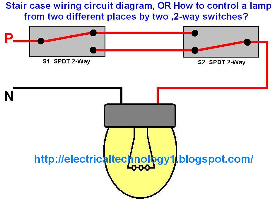

Also realize that wire size comes into play as you increase total current delivered into the parallel circuit. LEDs themselves don't need 12V to operate so the range of voltages a fixture will run depends on how many LED elements they use and how they wire them internally as well as any regulation they use.īut generally you wire 12V devices in parallel because they are designed to work individually and you can string as many in parallel as you want up to the limit of the switch (use a relay!) and battery. You'll see this specified with a range of voltages, e.g. The hot source (of the first 2-wire cable) is connected to the common terminal of the first switch (to the left, in the diagram).

WIRING LIGHTS IN PARALLEL WITH ONE SWITCH DIAGRAM FULL
A parallel circuit is also a closed circuit where the current divides into two or more paths before coming back together to complete the full circuit.

You can sometimes wire LEDs in series, which might be preferred if that is intended by their design. Much more common than series circuits are those wired in parallelincluding most household branch circuits powering light fixtures, outlets, and appliances. That means 12V/4Ω = 3A flows in the circuit and since 12V is common to all 3 bulbs that means 1A will flow through each. In the parallel circuit the battery will see the combination of three 12Ω loads in parallel, which is 1 / 1/R1 + 1/R2 + 1/R3. But Ohm's Law is conserved, 4V/0.333A = 12Ω thus the resistance remains correct. Each bulb would drop 4V and run dim or not at all in the case of LED. That would mean in the series circuit the battery (assuming 12V) sees 12Ω + 12Ω + 12Ω = 36Ω and the current would be 12V/36Ω = 0.333 amps. Let's say all the bulbs in those diagrams are designed for nominal 12 volt use and consume 1 amp, which implies their equivalent resistance is 12V/1A = 12Ω. Wired in series the voltage divides with each load voltage drop additive to the battery voltage. Wired in parallel all the loads see the battery voltage and the current divides.


 0 kommentar(er)
